Cam Followers Engineering Data
Cam Followers
For more details and a current listing of parts, please visit: Cam Followers
Selection Guide
Cam Followers are presented in five groups: Needle Roller Cam Followers; Caged Roller Followers; RBC Roller®; Long Life Cam Followers; Material Handling Rollers and Sheaves; and Airframe Track Rollers and Needle Bearings. RBC also produces a wide range of custom designed cam followers and track rollers. Designers and users with unusual application requirements should contact RBC to discuss custom designed cam followers.
| Application Requirements |
Needle Roller Cam Followers | Caged Roller Follower |
RBC Roller |
|||||
| Standard Stud |
Heavy Stud |
Yoke Type |
Cam- Centric |
Crowned Outer Ring |
||||
| Dynamic loading |
Mod | ✔ | ✔ | ✔ | ||||
| Heavy | ✔ | ✔ | ||||||
| Very Heavy |
✔ | |||||||
| Shock Loading | ✔ | ✔ | ||||||
| High Static Loads | ✔ | ✔ | ||||||
| Contamination | ✔ | |||||||
| Maintenance Free | ✔ | |||||||
| Long Life | ✔ | ✔ | ||||||
| Misalignment | ✔ | ✔ | ||||||
| Load Sharing | ✔ | |||||||
| Adjustability | ✔ | |||||||
| High Speed | ✔ | ✔ | ||||||
| Low Friction | ✔ | |||||||
| Circular Track | ✔ | |||||||
RBC Roller®
The RBC Roller® was developed for applications where long cam follower life and maintenance-free service are essential. They are dimensionally interchangeable with needle roller cam followers. The RBC Roller® is a good selection for production machinery applications where down time is critical and must be avoided, or where cam followers are not readily accessible for relubrication or replacement. They are available in stud type and yoke type configurations.
Two paths of end-guided, cylindrical rollers provide substantial increases in fatigue life and limiting speed. They can tolerate higher thrust loads than needle roller cam followers. Standard contacting lip seals offer enhanced protection against contaminants and positive grease retention. A large internal grease cavity assures maintenance-free service. Hex sockets are a standard feature. Crowned outer rings are available as an option.
Hexlube®
RBC stud type cam followers have a new Hexlube® feature and come equipped with a grease fitting installed in the flanged end of the stud. This permits relubrication through the hex head.
Standard Stud cam followers offer the mounting convenience of a threaded stud and are designed to accommodate moderate loads. They are available with and without seals. Standard stud cam followers are also available with crowned outer rings for applications where misalignment is a problem.
Heavy Stud cam followers are designed to provide additional stud strength for applications with high loading or shock loads. Heavy stud cam followers are available with and without seals, and with crowned outer rings.
Yoke Type cam followers are intended primarily for applications where loading conditions exceed the capabilities of stud type cam followers, or where clevis mounting is desired. Clevis mounting provides support on both sides of the cam follower and permits use of a high strength pin. Yoke type cam followers are available with and without seals, and with crowned outer rings.
Cam-Centric™ adjustable cam followers are used where accurate positioning is required. They are particularly useful for reducing clearance or backlash in opposed arrangements, and for assuring load sharing in multiple cam follower installations. Seals and hex socket are standard features of Cam-Centric™ adjustable cam followers. Crowned outer rings are also available.
Crowned Outer Rings are used to minimize outer ring thrusting in applications where the axis of the cam follower is not parallel to the surface of the track or is skewed relative to the direction of travel. Crowned outer rings are a good selection for use with curved or circular tracks. In well aligned applications, crowned outer rings can cause accelerated track wear.
Caged Roller Followers
Caged roller followers provide large internal grease storage capacity for applications where relubrication is infrequent. Cage guided rollers and a very heavy outer ring cross section permit operation at high loads and high speeds. Caged roller followers are available with and without seals. The unsealed design provides the additional advantages of very low friction to prevent skidding in lightly loaded applications and flow-through lubrication.
Caged roller followers normally mount directly on a hardened and ground pin. RBC offers a line of Precision Ground Inner Rings to simplify application of caged roller followers.
Material Handling Rollers and Sheaves
RBC offers a wide range of rollers and sheaves specifically designed for material handling applications-lifting, conveying, and power transmission. All RBC rollers and sheaves use heavy duty roller bearing construction which provides maximum dynamic and shock capacity for longer service life than ball bearing designs.
Lift Truck, Crane and Conveyor Rollers commonly referred to as mast guide rollers or carriage rollers, are used in lift truck masts and carriages, travelling cranes, and conveyor lines, where maximum capacity in an anti-friction roller is required. Sealed, lubricated-for-life versions are available.
Chain Sheave and Sprocket Idlers for BL-leaf and ANSI "rollerless" roller hoisting chain are essential components of hoisting systems such as lift trucks and car lifts. They are also used as track rollers and as tensioners in power transmission chain drives.
Airframe Track Rollers and Needle Bearings
Airframe track rollers and needle bearings are designed for high load carrying capability, light weight, and slow rotation or oscillatory motion. The exposed surfaces are plated to provide corrosion resistance. They are used in aircraft flap, slat and control applications, and in numerous non-aircraft applications.
Series NBC needle bearings offer high capacity, thin cross section and unitized construction. They are commonly used in pivots and linkages.
Series NBE and NBK needle bearings provide a spherical aligning outer ring to allow for misalignment. Applications and performance characteristics are otherwise similar to series NBC.
Series NBF and NBL track rollers are designed with heavy outer ring cross section for track roller applications. They offer a corrosion resistant alternative to conventional yoke type cam followers.
Difference from Standard Bearings
The outer rings of regular ball and roller bearings are typically mounted in rigid housings providing support around the entire circumference. Individual roller forces are transmitted through the outer ring directly into the housing with no major deformations.
By contrast, cam followers and yoke rollers are supported at a single point on their circumference. Individual roller forces produce bending moments on the outer ring around the point of contact. The effects are outer ring deformation with reversed bending stresses in dynamic applications, a reduced load zone, and a higher maximum roller load. See Figure 1.
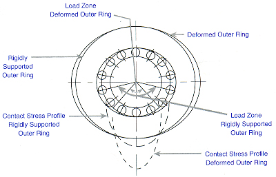
Load Zone & Maximum
Figure 1.
To keep deformation to a minimum, the outer ring of a cam follower must have a considerably heavier cross section than a standard bearing. This requirement conflicts with the desire for maximum dynamic bearing capacity which needs as large a roller diameter as possible. RBC cam followers and yoke rollers provide an optimum compromise between outer ring strength and theoretical bearing capacity.
Capacity and Load Limits
Evaluation of the expected service life and limit loads of cam followers is more complex than with housed bearings. In addition to the static and dynamic capacity of the rolling elements, outer ring deformation, track capacity, and cam follower stud bending stress must be considered. In yoke rollers, the pin shear stress must be considered.
Although RBC lists the static bearing capacity for comparative purposes, in most cases the applied loads will be limited by stud strength, pin strength, or track strength.
2.1 Capacity of Rolling Element Bearing
Equations for static and dynamic capacities of roller bearings are given in ANSI/ABMA Standard 11. The more recent revisions leave it up to the manufacturer to introduce factors which account for internal design features and operating conditions. For cam followers and yoke rollers RBC has chosen to apply a conservative rating system, so a direct comparison with capacity figures of competitive products may not be possible.
2.2 Track Capacity
Track capacity is that load which a track subject to a uniform contact stress can withstand without excessive plastic deformation. It is directly related to track hardness. The published track capacity is based on a hardness of HRc 40. For other track hardness values the track capacity must be modified with factors from Table 1.
| Track Hardness [HRc] |
Material Strength [psi] |
Modification [Factor] |
| 26 | 128 | .45 |
| 32 | 146 | .61 |
| 36 | 165 | .76 |
| 40 | 182 | 1.00 |
| 44 | 204 | 1.24 |
| 47 | 229 | 1.50 |
| 50 | 247 | 1.78 |
| 53 | 266 | 2.09 |
| 56 | 281 | 2.42 |
| 58 | 298 | 2.78 |
Table 1: Track Capacity Adjustment Factors
Alternatively, contact stress can be easily calculated and compared directly to the strength of material. The equation for the Hertz contact stress between a cylindrical cam follower outer ring and a flat steel track is given by "Roark, Formulas for Stress and Strain" as:

|
where |
F = radial load [lbf]
|
It can be shown that for infinite life the ultimate tensile strength of track and roller must be at least equal to the maximum contact stress σc max .
Example 1.
Determine the required minimum track hardness for an RBC cam follower S 56 L operating under a 3000 lbf radial load.
Solution:

Referring to Table 1, 149,800 psi is between 146,00 psi (HRc 32) and 165,000 psi (HRc 36). Interpolation yields minimum track hardness of HRc 33.
Fatigue Life
Fatigue life, L10 [rev, hrs], is a statistical measure of the life which 90% of a large group apparently identical rolling element bearings will complete or exceed. For a single bearing, L10 also refers to the life associated with 90% reliability.
The relationship between fatigue or rating life, capacity and load is:

|
where |
L10 rev = Rating Life [106 rev]
|
To obtain the rating life in [hours], use
|
where |
L10 hrs = Rating Life [hours]
|
In case of constant speed, the equivalent speed equals the constant bearing speed. In all other cases the quivalent speed is the weighted average of all individual speed components.

|
where |
ni = individual speed component [rpm]
|
In cases of constant load, the equivalent radial load equals the constant load. To compute the equivalent load for all other cases, use:
|
where |
q = 10/3 for roller bearings
|
Speed Limit and Maximum Acceleration
4.1 Speed Limit
The limiting speed of rolling element bearings is primarily a function of size and internal design. The speed limits given in this catalog should not be exceeded on a continuous basis to prevent premature failure due to excessive temperature. Contact RBC for solutions to high speed applications.
4.2 Maximum Acceleration (Deceleration)
|
where |
μ = coefficient of friction (outer ring to track) |
The force Ft produces a moment Mt, which must accelerate the masses of outer ring and rollers around the bearing axis, plus the rollers in the load zone around their own axes.
The movement Mt can be calculated using:
Accelerating the mass of the outer ring normally requires the largest part of moment Mt. Assuming a coefficient of friction of m = 0.10 and a typical cam follower design, the following equation may be used for an estimate of the permissible angular acceleration a:
Excessive acceleration causes sliding of the outer ring on the track. The effects range from minor uniform wear on cam follower and track to flat spots on the cam follower with subsequent failure.
Speed Limit and Maximum Acceleration
5.1 Cam Followers
For greatest rigidity and strength, the end plate should be drawn up snugly against a boss or other flat surface of the housing. The tables on pages 5 throughout 27 list maximum recommended clamping torque for lubricated threads, which is the normal condition. Use up to twice the listed torque for completely dry threads.
The housing bore should be drilled and reamed to the recommended tolerance. If a greater tolerance is needed, it should be added to the plus side to prevent cam follower damage during assembly. If the cam follower stud fits tightly into the housing bore, use an arbor press and apply pressure against the central portion of the flange. Never press against the rim of the flange or the outer ring.
Although wide blade screwdrivers may be used to hold cam followers during assembly, rounded tools conforming to the slot are preferable to avoid plastic deformation in the slot area.
RBC offers a convenient socket (W suffix) for hex wrenches to provide a more substantial grip, especially for 'blind hole' applications. (Note this series can only be relubricated from the thread end or through the housing).
5.2 Eccentric Cam Followers
Eccentric cam followers are used when there is a need to make height adjustments between the cam follower and the track. By simply turning the entire cam follower inside the housing it is possible to adjust the distance between the cam follower and the track by twice the eccentricity. However, due to the mechanical advantage that the eccentricity provides, it is inadvisable that the cam follower be adjusted over this entire range.
A very large force can be exerted on the track for a small applied adjusting torque as the eccentricity of the cam follower approaches ±90 degrees from a starting position parallel to the track, in the housing. Adjustments should be limited to ±45 degrees and the resulting preload should not exceed 10% of the cam followers capacity.
The following equation can be used to find an appropriate adjusting torque.

|
where |
T = appropriate adjusting torque [lbf]
|
Example 5. Cam-centric cam follower S48LWX has a dynamic capacity of 4,600 lb, and an eccentricity of 0.03 in. Determine the appropriate adjusting torque.
Solution:
5.3 Yoke Rollers
RBC yoke rollers correspond in many respects to the same size cam follower, except they are mounted on a pin for use in yoke type applications for greater shock resistance.
Yoke rollers should be clamped axially or mounted within closely fitting side rails to prevent displacement of the end plates. For applications with heavy loads, it is recommended to heat treat the pin and use a press fit for the inner ring. A soft pin and light press or push fit are sufficient for lightly loaded applications. When press fitting a yoke roller, pressure should be applied centrally and uniformly against the end plate, never against the outer ring.
The pin should have a suitable lead-in chamfer or radius to prevent scoring and to hold the mounting force to a minimum.
5.4 Caged Roller Followers
Caged roller followers can operate directly on a hardened and ground shaft (HRc 58 min, 16 rms min surface finish) or can be used with matching inner rings. Operating without an inner ring yields the largest possible shaft diameter with greatest strength and rigidity. Axial guidance must be provided by the application. It is recommended to use hardened steel or bronze thrust washers with radial lubricating grooves as needed.
Lubrication
Cam followers and yoke rollers are pre-lubricated with an NLGI grade 2, lithium soap, mineral oil based grease with EP additives. RBC Roller type cam followers and yoke rollers are normally lubricated for life and have no provisions for relubrication. Needle roller type cam followers require relubrication depending on operating speed, duty cycle, operating environment, desired service life, etc.
For relubrication in service, mineral oil, or any good roller bearing grease on mineral oil basis may be used. Inquire about compatibility of greases with different base oil and thickener.
Except for the very small sizes (see tables), cam followers with screwdriver slots can be relubricated from both ends of the stud and through the housing. Table 2 lists suitable drive fit Alemite fittings. Plugs are furnished by RBC to close off unused passages.
| Size | Bearing P/N | Fitting P/N |
| 1/2" - 11/16" | -16 to -22 | 3019 |
| 3/4" - 2 3/4" | -24 to -88 | 1728-B, 1645-B |
| 3" - 4" | -96 to -128 | 1743, 1743-B |
| 5" - up | -160 | any 1/4" NPT Fitting |
Cam followers with hex holes cannot be relubricated from the flange end. Yoke rollers and sealed roller followers must be relubricated through the shaft.
Misalignment
Initial misalignment should not exceed .001 in./in. Any misalignment generates thrust forces between outer ring and flange or end plate. Excessive thrusting can lead to increased operating temperature and destruction of the seal in standard cam followers and yoke rollers. Where misalignment and outer ring thrusting cannot be avoided, RBC recommends crowned outer rings or the RBC Roller design which is more capable to withstand thrust loads.
Operating Temperature
The temperature limits of all standard cam followers and yoke rollers in this catalog, except airframe bearings, are determined by the temperature limits of the seals and the lubricant. The normal operating temperature ranges from -20° F (-29° C) to +250° F (120° C). For short periods the maximum temperature may rise to +300° F (150° C). Cam followers and yoke rollers without RBC's Glide-A-Seal® still contain a plastic glide pad between outer ring and flange or end plate which is subject to the same temperature limitations.
RBC can provide special solutions for applications outside the normal operating temperature range.