Self-Lubricating Bearings Engineering Data
Self Lubricating Bearings
For more details and a current listing of parts, please visit:
Self-Lubricating Bearings - FIBERGLIDE®
Table of Contents
- Selection Guide
-
Engineering Data
- Design Calculations
- Bearing Wear
- Bearing Load Limits
- Velocity Limit
- PV Factor
- Temperature Limit
- Coefficient of Thermal Expansion
- Mating Surfaces
- Coefficient of Friction
- Contamination
- Running Clearance
- Bearing Housing and Shaft Sizing
- Fluid Compatibility
- Metric Technical Data Conversions
RBC Bearings is the leader in self-lubricating technology with our patented FIBERGLIDE® liners. We produce a broad line of standard inch and metric self-lubricating bearings in journal and thrust configurations. This unique bearing product offers the user design freedom as well as cost benefits from its “maintenance free” characteristics.
The self-lubricating thrust and journal bearings are suited for applications where normal lubrication is difficult or costly. FIBERGLIDE® lined thrust and journal bearings are designed to be used under oscillating motion, interrupted start-stop, or axial motion. They are recommended where high loads are combined with low surface speeds. FIBERGLIDE® products can also be used where non-lubricating fluids might be present.
The self-lubricating thrust and journal bearings are suited for applications where normal lubrication is difficult or costly. FIBERGLIDE® lined thrust and journal bearings are designed to be used under oscillating motion, interrupted start-stop, or axial motion. They are recommended where high loads are combined with low surface speeds. FIBERGLIDE® products can also be used where non-lubricating fluids might be present.
For bearing installation click here.
Self Lubricating Bearings Selection Guide
| Type | Description | Dimensions | Applications |
|---|---|---|---|
 |
CJS Journal bearings, coiled steel backing, zinc plated. |
Nom.
shaft diameter- .375 to 10.000 Bearing length- . 250 to 6.50 Wall thickness- .045 to .093 |
The CJS bearing works excellent in any pivot or linkage application. For construction and farm equipment, this product is typically used in kingpins, rock shafts, differentials, hinges, pedals and many other pivot points. |
 |
CJT Journal bearings,thin walled, coiled steel backing, zinc plated |
Nom.
shaft diameter- .500 to 10.000 Bearing length- .375 to 6.50 Wall thickness - .060 |
This bearing is designed as a direct replacement with conventional 1/16" wall bushings. These bearings are used in self-lubricated chain, variable speed sheaves, boom pivot points on fork lifts and many similar applications. |
 |
CJH Journal bearings, heavy walled, coiled steel backing, zinc plated |
Nom.
shaft diameter- .750 to 10.000 Bearing length - .375 to 11.00 Wall thickness - .125 |
This bearing is designed as a direct replacement with the conventional 1/8" wall bronze bushings. Typical applications include suspension points on large trucks and railroad cars. These products are also used in the boom foot pivot of large cranes. |
 |
CJM Metric Journal bearings, coiled steel backing, zinc plated |
Nom.
shaft diameter- 8MM to 120MM Bearing length- 8MM to 165MM Wall thickness- 1.0 to 2.5MM |
This product is the metric equivalent to the CJS product and used in similar applications. |
 |
LJS Journal bearings, liner type, non-metallic |
Nom.
shaft diameter- 1.000 to 12.000 Bearing length- .375 to 6.50 Wall thickness- .022 to .062 |
These bearings are used in many harsh applications and in food handling machinery. Typical applications include butterfly valves and trunnion support pivots. This product is also used in sheaves and hoists for marine applications. |
 |
FTS Thrust bearings, metal-backed, single sided |
Nom.
shaft diameter- .250 to 3.250 I.D. - .280 to 3.312 O.D. - .500 to 4.875 Thickness- .030 to .060 |
These bearings accommodate thrust in clutches, hospital beds, screw jacks, valve actuators, vehicle suspensions, and many other applications. |
|
LTD Thrust bearings, laminated phenolic-backed, double-sided |
Nom.
shaft diameter- .250 to 3.250 I.D. - .280 to 3.312 O.D. - .500 to 4.875 Thickness- .030 to .094 |
These bearings are used in cam actuator arms, turntable support bearings, exercise equipment, truck differentials and many other applications. |
|
FTP Thrust packs, Two piece assembly |
I.D.
- 1.000 to 3.000 O.D. -1.750 to 4.625 Thickness- .130 |
These bearings are used in articulated frame joints, pivot arm supports, kingpins and many other applications. |
 |
SJR Sealed Journal Brgs. solid cold rolled steel sleeve with two polyurethane seals. |
Nom.
shaft diameter- 1.000 to 5.000 Bearing length- 1.000 - 4.000 Wall thickness- .250 - .375 |
These bearings are used in crane boom foot positions, wheels and pallet jacks, frame supports for large trucks and other construction equipment and many other applications. |
Coiled Steel Backing
FIBERGLIDE® coiled steel journal bearings are designed to meet industry standards for self-lubricating bushings. They provide all of the advantages of FIBERGLIDE® at minimum cost. Carbon steel is normally used as a backing material, with the external surfaces plated to resist corrosion. Other metals can be supplied upon special order. Typical applications include automotive vehicles, farm equipment, construction and material handling equipment.
FABROID® can also be supplied for special applications - consult Transport Dynamics Engineering Department.
| Part Number | Maximum Shaft Diameter |
Recommended Housing Bore Min/Max |
Bearing Length |
| CJS0606 | 0.375 | .4680/.4690 | 0.375 |
| CJS0608 | 0.375 | .4680/.4690 | 0.500 |
| CJS0610 | 0.375 | .4680/.4690 | 0.625 |
| CJS0612 | 0.375 | .4680/.4690 | 0.750 |
| CJS0808 | 0.500 | .5930/.5940 | 0.500 |
| CJS0810 | 0.500 | .5930/.5940 | 0.625 |
| CJS0812 | 0.500 | .5930/.5940 | 0.750 |
| CJS0816 | 0.500 | .5930/.5940 | 1.000 |
| CJS1008 | 0.625 | .7180/.7190 | 0.500 |
| CJS1010 | 0.625 | .7180/.7190 | 0.625 |
| CJS1012 | 0.625 | .7180/.7190 | 0.750 |
| CJS1016 | 0.625 | .7180/.7190 | 1.000 |
| CJS1208 | 0.750 | .8745/.8755 | 0.500 |
| CJS1212 | 0.750 | .8745/.8755 | 0.750 |
| CJS1216 | 0.750 | .8745/.8755 | 1.000 |
| CJS1220 | 0.750 | .8745/.8755 | 1.250 |
| CJS1408 | 0.875 | .9995/1.0005 | 0.500 |
| CJS1414 | 0.875 | .9995/1.0005 | 0.875 |
| CJS1416 | 0.875 | .9995/1.0005 | 1.000 |
| CJS1420 | 0.875 | .9995/1.0005 | 1.25 |
| CJS1608 | 1.000 | 1.1245/1.1255 | 0.500 |
| CJS1612 | 1.000 | 1.1245/1.1255 | 0.750 |
| CJS1616 | 1.000 | 1.1245/1.1255 | 1.000 |
| CJS1620 | 1.000 | 1.1245/1.1255 | 1.250 |
| CJS1624 | 1.000 | 1.1245/1.1255 | 1.500 |
| CJS1812 | 1.125 | 1.2805/1.2815 | 0.750 |
| CJS1816 | 1.125 | 1.2805/1.2815 | 1.000 |
| CJS1818 | 1.125 | 1.2805/1.2815 | 1.125 |
| CJS1824 | 1.125 | 1.2805/1.2815 | 1.500 |
| CJS2012 | 1.250 | 1.4055/1.4065 | 0.750 |
| CJS2016 | 1.250 | 1.4055/1.4065 | 1.000 |
| CJS2020 | 1.250 | 1.4055/1.4065 | 1.250 |
| CJS2024 | 1.250 | 1.4055/1.4065 | 1.500 |
| CJS2212 | 1.375 | 1.5305/1.5315 | 0.750 |
| CJS2216 | 1.375 | 1.5305/1.5315 | 1.000 |
| CJS2222 | 1.375 | 1.5305/1.5315 | 1.375 |
| CJS2224 | 1.375 | 1.5305/1.5315 | 1.500 |
| CJS2416 | 1.500 | 1.6555/1.6565 | 1.000 |
| CJS2424 | 1.500 | 1.6555/1.6565 | 1.500 |
| CJS2428 | 1.500 | 1.6555/1.6565 | 1.750 |
| CJS2816 | 1.750 | 1.9375/1.9385 | 1.000 |
| CJS2824 | 1.750 | 1.9375/1.9385 | 1.500 |
| CJS2828 | 1.750 | 1.9375/1.9385 | 1.750 |
| CJS2832 | 1.750 | 1.9375/1.9385 | 2.000 |
| CJS3216 | 2.000 | 2.1875/2.1885 | 1.000 |
| CJS3224 | 2.000 | 2.1875/2.1885 | 1.500 |
| CJS3232 | 2.000 | 2.1875/2.1885 | 2.000 |
| CJS3618 | 2.250 | 2.4375/2.4385 | 1.125 |
| CJS3636 | 2.250 | 2.4375/2.4385 | 2.250 |
| CJS4020 | 2.500 | 2.6875/2.6885 | 1.250 |
| CJS4040 | 2.500 | 2.6875/2.6885 | 2.500 |
| CJS4422 | 2.750 | 2.9375/2.9385 | 1.375 |
| CJS4444 | 2.750 | 2.9375/2.9385 | 2.750 |
| CJS4824 | 3.000 | 3.1875/3.1885 | 1.500 |
| CJS4848 | 3.000 | 3.1875/3.1885 | 3.000 |
| CJS5628 | 3.500 | 3.6875/3.6885 | 1.750 |
| CJS5656 | 3.500 | 3.6875/3.6885 | 3.500 |
| CJS6432 | 4.000 | 4.1875/4.1885 | 2.000 |
| CJS6464 | 4.000 | 4.1875/4.1885 | 4.000 |
| Part Number | Shaft Diameter Min/Max |
Recommended Housing Bore Min/Max |
Bearing Length |
| CJM0808 | 7.972/7.987 | 10.000/10.015 | 8.00 |
| CJM0810 | 7.972/7.987 | 10.000/10.015 | 10.00 |
| CJM0812 | 7.972/7.987 | 10.000/10.015 | 12.00 |
| CJM1008 | 9.972/9.987 | 12.000/12.018 | 8.00 |
| CJM1010 | 9.972/9.987 | 12.000/12.018 | 10.00 |
| CJM1012 | 9.972/9.987 | 12.000/12.018 | 12.00 |
| CJM1015 | 9.972/9.987 | 12.000/12.018 | 15.00 |
| CJM1020 | 9.972/9.987 | 12.000/12.018 | 20.00 |
| CJM1208 | 11.966/11.984 | 14.000/14.018 | 8.00 |
| CJM1210 | 11.966/11.984 | 14.000/14.018 | 10.00 |
| CJM1212 | 11.966/11.984 | 14.000/14.018 | 12.00 |
| CJM1215 | 11.966/11.984 | 14.000/14.018 | 15.00 |
| CJM1220 | 11.966/11.984 | 14.000/14.018 | 20.00 |
| CJM1225 | 11.966/11.984 | 14.000/14.018 | 25.00 |
| CJM1310 | 12.966/12.984 | 15.000/15.018 | 10.00 |
| CJM1415 | 13.966/13.984 | 16.000/16.018 | 15.00 |
| CJM1420 | 13.966/13.984 | 16.000/16.018 | 20.00 |
| CJM1512 | 14.966/14.984 | 17.000/17.018 | 12.00 |
| CJM1515 | 14.966/14.984 | 17.000/17.018 | 15.00 |
| CJM1525 | 14.966/14.984 | 17.000/17.018 | 25.00 |
| CJM1612 | 15.966/15.984 | 18.000/18.018 | 12.00 |
| CJM1615 | 15.966/15.984 | 18.000/18.018 | 15.00 |
| CJM1620 | 15.966/15.984 | 18.000/18.018 | 20.00 |
| CJM1625 | 15.966/15.984 | 18.000/18.018 | 25.00 |
| CJM1815 | 17.966/17.984 | 20.000/20.021 | 15.00 |
| CJM1820 | 17.966/17.984 | 20.000/20.021 | 20.00 |
| CJM1825 | 17.966/17.984 | 20.000/20.021 | 25.00 |
| CJM2015 | 19.959/19.980 | 23.000/23.021 | 15.00 |
| CJM2020 | 19.959/19.980 | 23.000/23.021 | 20.00 |
| CJM2025 | 19.959/19.980 | 23.000/23.021 | 25.00 |
| CJM2030 | 19.959/19.980 | 23.000/23.021 | 30.00 |
| CJM2215 | 21.959/21.980 | 25.000/25.021 | 15.00 |
| CJM2220 | 21.959/21.980 | 25.000/25.021 | 20.00 |
| CJM2225 | 21.959/21.980 | 25.000/25.021 | 25.00 |
| CJM2230 | 21.959/21.980 | 25.000/25.021 | 30.00 |
| CJM2415 | 23.959/23.980 | 27.000/27.021 | 15.00 |
| CJM2420 | 23.959/23.980 | 27.000/27.021 | 20.00 |
| CJM2425 | 23.959/23.980 | 27.000/27.021 | 25.00 |
| CJM2430 | 23.959/23.980 | 27.000/27.021 | 30.00 |
| CJM2515 | 24.959/24.980 | 28.000/28.021 | 15.00 |
| CJM2520 | 24.959/24.980 | 28.000/28.021 | 20.00 |
| CJM2525 | 24.959/24.980 | 28.000/28.021 | 25.00 |
| CJM2530 | 24.959/24.980 | 28.000/28.021 | 30.00 |
| CJM2550 | 24.959/24.980 | 28.000/28.021 | 50.00 |
Thin-Walled Coiled Steel Backing
The constant wall thickness of .062 of the CJT SERIES makes them dimensionally interchangeable with other types of coiled bearings commonly used. They provide all the advantages of FIBERGLIDE® at minimum cost. Carbon steel is normally used as a backing material, with the external surfaces plated to resist corrosion. Other metals can be supplied upon special order. Typical applications include automotive vehicles, farm equipment, construction and material handling equipment.
A FABROID® Liner can also be supplied for special applications-consult Transport Dynamics Engineering Department.
* Recommended housing bores are for steel housings. Contact Engineering for recommended housing dimensions for alternate materials.
| Part Number | Maximum Shaft Diameter |
Recommended Housing Bore Min/Max |
Bearing Length |
| CJT0808 | 0.500 | .6240/.6250 | 0.500 |
| CJT0810 | 0.500 | .6240/.6250 | 0.625 |
| CJT0812 | 0.500 | .6240/.6250 | 0.750 |
| CJT0816 | 0.500 | .6240/.6250 | 1.000 |
| CJT1008 | 0.625 | .7490/.7500 | 0.500 |
| CJT1010 | 0.625 | .7490/.7500 | 0.625 |
| CJT1012 | 0.625 | .7490/.7500 | 0.750 |
| CJT1016 | 0.625 | .7490/.7500 | 1.000 |
| CJT1812 | 1.125 | 1.2495/1.2505 | 0.750 |
| CJT1816 | 1.125 | 1.2495/1.2505 | 1.000 |
| CJT1818 | 1.125 | 1.2495/1.2505 | 1.125 |
| CJT1824 | 1.125 | 1.2495/1.2505 | 1.500 |
| CJT2012 | 1.250 | 1.3745/1.3755 | 0.750 |
| CJT2016 | 1.250 | 1.3745/1.3755 | 1.000 |
| CJT2020 | 1.250 | 1.3745/1.3755 | 1.250 |
| CJT2024 | 1.250 | 1.3745/1.3755 | 1.500 |
| CJT2212 | 1.375 | 1.4995/1.5005 | 0.750 |
| CJT2216 | 1.375 | 1.4995/1.5005 | 1.000 |
| CJT2222 | 1.375 | 1.4995/1.5005 | 1.375 |
| CJT2224 | 1.375 | 1.4995/1.5005 | 1.500 |
| CJT2416 | 1.500 | 1.6245/1.6255 | 1.000 |
| CJT2424 | 1.500 | 1.6245/1.6255 | 1.500 |
| CJT2428 | 1.500 | 1.6245/1.6255 | 1.750 |
| CJT2816 | 1.750 | 1.8745/1.8755 | 1.000 |
| CJT2824 | 1.750 | 1.8745/1.8755 | 1.500 |
| CJT2828 | 1.750 | 1.8745/1.8755 | 1.750 |
| CJT2832 | 1.750 | 1.8745/1.8755 | 2.000 |
| CJT3216 | 2.000 | 2.1245/2.1255 | 1.000 |
| CJT3224 | 2.000 | 2.1245/2.1255 | 1.500 |
| CJT3232 | 2.000 | 2.1245/2.1255 | 2.000 |
| CJT3618 | 2.250 | 2.3745/2.3755 | 1.125 |
| CJT3636 | 2.250 | 2.3745/2.3755 | 2.250 |
| CJT4020 | 2.500 | 2.6245/2.6255 | 1.250 |
| CJT4040 | 2.500 | 2.6245/2.6255 | 2.500 |
| CJT4422 | 2.750 | 2.8745/2.8755 | 1.375 |
| CJT4444 | 2.750 | 2.8745/2.8755 | 2.750 |
| CJT4824 | 3.000 | 3.1245/3.1255 | 1.500 |
| CJT4848 | 3.000 | 3.1245/3.1255 | 3.000 |
| CJT5226 | 3.250 | 3.3745/3.3755 | 1.625 |
| CJT5252 | 3.250 | 3.3745/3.3755 | 3.250 |
| CJT5628 | 3.500 | 3.6245/3.6255 | 1.750 |
| CJT5656 | 3.500 | 3.6245/3.6255 | 3.500 |
| CJT6030 | 3.750 | 3.8745/3.8755 | 1.875 |
| CJT6060 | 3.750 | 3.8745/3.8755 | 3.750 |
| CJT6432 | 4.000 | 4.1245/4.1255 | 2.000 |
| CJT6464 | 4.000 | 4.1245/4.1255 | 4.000 |
Heavy Wall Coiled Steel Backing
The constant wall thickness of 1/8 in. (.125) for the CJH Series makes them dimensionally interchangeable with many bronze bushings. Carbon steel is normally used as a backing material, with the external surface plated to resist corrosion. Other materials can be supplied upon special order. Typical applications include farm equipment, construction and material handling equipment.
FABROID® can also be supplied for special applications. Consult Transport Dynamics Engineering Department.
* Recommended housing bores are for steel housings. Contact Engineering for recommended housing dimensions for alternate materials.
| Part Number | Maximum Shaft Diameter |
Recommended Housing Bore Min/Max |
Bearing Length |
| CJH1204 | 0.750 | .9995/1.0005 | 0.250 |
| CJH1208 | 0.750 | .9995/1.0005 | 0.500 |
| CJH1212 | 0.750 | .9995/1.0005 | 0.750 |
| CJH1608 | 1.000 | 1.2495/1.2505 | 0.500 |
| CJH1612 | 1.000 | 1.2495/1.2505 | 0.750 |
| CJH1616 | 1.000 | 1.2495/1.2505 | 1.000 |
| CJH1812 | 1.125 | 1.3745/1.3755 | 0.750 |
| CJH1816 | 1.125 | 1.3745/1.3755 | 1.000 |
| CJH2016 | 1.250 | 1.4995/1.5005 | 1.000 |
| CJH2020 | 1.250 | 1.4995/1.5005 | 1.250 |
| CJH2024 | 1.250 | 1.4995/1.5005 | 1.500 |
| CJH2216 | 1.375 | 1.6245/1.6255 | 1.00 |
| CJH2220 | 1.375 | 1.6245/1.6255 | 1.25 |
| CJH2224 | 1.375 | 1.6245/1.6255 | 1.50 |
| CJH2420 | 1.500 | 1.7495/1.7505 | 1.250 |
| CJH2424 | 1.500 | 1.7495/1.7505 | 1.500 |
| CJH2432 | 1.500 | 1.7495/1.7505 | 2.000 |
| CJH2820 | 1.750 | 1.9995/2.0005 | 1.250 |
| CJH2824 | 1.750 | 1.9995/2.0005 | 1.500 |
| CJH2832 | 1.750 | 1.9995/2.0005 | 2.000 |
| CJH3224 | 2.000 | 2.2495/2.2505 | 1.500 |
| CJH3232 | 2.000 | 2.2495/2.2505 | 2.000 |
| CJH3248 | 2.000 | 2.2495/2.2505 | 3.000 |
| CJH3624 | 2.250 | 2.4995/2.5005 | 1.500 |
| CJH3632 | 2.250 | 2.4995/2.5005 | 2.000 |
| CJH3648 | 2.250 | 2.4995/2.5005 | 3.000 |
| CJH4032 | 2.500 | 2.7495/2.7505 | 2.000 |
| CJH4040 | 2.500 | 2.7495/2.7505 | 2.500 |
| CJH4048 | 2.500 | 2.7495/2.7505 | 3.000 |
| CJH4432 | 2.750 | 2.9995/3.0005 | 2.000 |
| CJH4440 | 2.750 | 2.9995/3.0005 | 2.500 |
| CJH4448 | 2.750 | 2.9995/3.0005 | 3.000 |
| CJH4832 | 3.000 | 3.2495/3.2505 | 2.000 |
| CJH4840 | 3.000 | 3.2495/3.2505 | 2.500 |
| CJH4848 | 3.000 | 3.2495/3.2505 | 3.000 |
| CJH5232 | 3.250 | 3.4995/3.5005 | 2.000 |
| CJH5240 | 3.250 | 3.4995/3.5005 | 2.500 |
| CJH5248 | 3.250 | 3.4995/3.5005 | 3.000 |
| CJH5632 | 3.500 | 3.7495/3.7505 | 2.000 |
| CJH5664 | 3.500 | 3.7495/3.7505 | 4.000 |
| CJH6032 | 3.750 | 3.9995/4.0005 | 2.000 |
| CJH6064 | 3.750 | 3.9995/4.0005 | 4.000 |
| CJH6432 | 4.000 | 4.2495/4.2505 | 2.000 |
| CJH6464 | 4.000 | 4.2495/4.2505 | 4.000 |
Liner Type Non-Metallic
The FIBERGLIDE® Liner Type bearing provides high load capacity and low friction in the form of a thin-walled sleeve for use in butterfly valves, trunnion bearings, ball and plug valve stem bushings, hydraulic and pneumatic cylinder guide bushings, food handling machinery, and door hinge bushings, among others.
Because these bearings are completely non-metallic-fabricated of woven PTFE fibers on the bore supported by a laminated backing-there is no possibility of corrosion. Maximum compressive strength is 10,000 psi, with operating temperature range of -250°F to 200°F. Maximum speeds are typically 20 surface FPM.
* Recommended housing bores are for steel housings. Contact Engineering for recommended housing dimensions for alternate materials.
| Part Number | Maximum Shaft Diameter |
Recommended Housing Bore Min/Max |
Wall Thickness |
Bearing Length |
| LJS1616 | 1.000 | 1.061/1.062 | .027/.030 | 1.000 |
| LJS1624 | 1.000 | 1.061/1.062 | .027/.030 | 1.500 |
| LJS1632 | 1.000 | 1.061/1.062 | .027/.030 | 2.000 |
| LJS1818 | 1.125 | 1.186/1.187 | .027/.030 | 1.125 |
| LJS1828 | 1.125 | 1.186/1.187 | .027/.030 | 1.500 |
| LJS1836 | 1.125 | 1.186/1.187 | .027/.030 | 2.250 |
| LJS2020 | 1.250 | 1.311/1.312 | .027/.030 | 1.250 |
| LJS2030 | 1.250 | 1.311/1.312 | .027/.030 | 1.875 |
| LJS2040 | 1.250 | 1.311/1.312 | .027/.030 | 2.500 |
| LJS2222 | 1.375 | 1.436/1.437 | .027/.030 | 1.375 |
| LJS2232 | 1.375 | 1.436/1.437 | .027/.030 | 2.000 |
| LJS2244 | 1.375 | 1.436/1.437 | .027/.030 | 2.750 |
| LJS2424 | 1.500 | 1.561/1.562 | .027/.030 | 1.500 |
| LJS2436 | 1.500 | 1.561/1.562 | .027/.030 | 2.250 |
| LJS2448 | 1.500 | 1.561/1.562 | .027/.030 | 3.000 |
| LJS2828 | 1.750 | 1.811/1.812 | .027/.030 | 1.750 |
| LJS2842 | 1.750 | 1.811/1.812 | .027/.030 | 2.625 |
| LJS2856 | 1.750 | 1.811/1.812 | .027/.030 | 3.500 |
| LJS3232 | 2.000 | 2.126/2.127 | .059/.062 | 2.000 |
| LJS3248 | 2.000 | 2.126/2.127 | .059/.062 | 3.000 |
| LJS3636 | 2.250 | 2.376/2.377 | .059/.062 | 2.250 |
| LJS3654 | 2.250 | 2.376/2.377 | .059/.062 | 3.375 |
| LJS4040 | 2.500 | 2.626/2.627 | .059/.062 | 2.500 |
| LJS4060 | 2.500 | 2.626/2.627 | .059/.062 | 3.750 |
| LJS4444 | 2.750 | 2.876/2.877 | .059/.062 | 2.750 |
| LJS4466 | 2.750 | 2.876/2.877 | .059/.062 | 4.125 |
| LJS4848 | 3.000 | 3.126/3.127 | .059/.062 | 3.000 |
| LJS4872 | 3.000 | 3.126/3.127 | .059/.062 | 4.500 |
| LJS5656 | 3.500 | 3.626/3.627 | .059/.062 | 3.500 |
| LJS5684 | 3.500 | 3.626/3.627 | .059/.062 | 5.250 |
| LJS6464 | 4.000 | 4.126/4.127 | .059/.062 | 4.000 |
| LJS6496 | 4.000 | 4.126/4.127 | .059/.062 | 6.000 |
| LJS7272 | 4.5 | 4.626/4.627 | .059/.062 | 4.500 |
| LJS8080 | 5 | 5.126/5.127 | .059/.062 | 5.000 |
| LJS8888 | 5.5 | 5.626/5.627 | .059/.062 | 5.500 |
| LJS9696 | 6 | 6.126/6.127 | .059/.062 | 6.000 |
Metal-Backed
FIBERGLIDE® FTS series thrust bearings offer an economical approach to obtaining self-lubrication where high loads are encountered. They are comprised of zinc-plated mild steel with woven PFTE laminated to one face. These bearings are recommended for use as an alternate to LTD washers in applications where metal backing is preferred.
Maximum compressive strength is 30,000 psi, with operating temperature range of -320°F to 300°F. Friction coefficients as low as 0.03 with no added lubricants are obtainable.
FABROID® Liners can also be supplied. For special applications, consult Transport Dynamics Engineering Department. These thrust bearings can also be supplied with special metals and with liners on both sides (FTD) series.
| Part Number | Maximum Shaft Diameter |
ID | OD | Thickness |
| FTS0408 | 0.25 | 0.28 | 0.5 | 0.058 |
| FTS0510 | 0.312 | 0.344 | 0.625 | 0.058 |
| FTS0612 | 0.375 | 0.406 | 0.75 | 0.058 |
| FTS0714 | 0.437 | 0.468 | 0.875 | 0.058 |
| FTS0816 | 0.5 | 0.531 | 1 | 0.058 |
| FTS0918 | 0.562 | 0.593 | 1.125 | 0.058 |
| FTS1020 | 0.625 | 0.656 | 1.25 | 0.058 |
| FTS1122 | 0.687 | 0.718 | 1.375 | 0.058 |
| FTS1224 | 0.75 | 0.781 | 1.5 | 0.058 |
| FTS1326 | 0.812 | 0.843 | 1.625 | 0.058 |
| FTS1428 | 0.875 | 0.906 | 1.75 | 0.058 |
| FTS1530 | 0.937 | 0.968 | 1.875 | 0.058 |
| FTS1632 | 1 | 1.031 | 2 | 0.058 |
| FTS1834 | 1.125 | 1.156 | 2.125 | 0.058 |
| FTS2036 | 1.25 | 1.281 | 2.25 | 0.058 |
| FTS2240 | 1.375 | 1.406 | 2.5 | 0.058 |
| FTS2442 | 1.5 | 1.531 | 2.625 | 0.058 |
| FTS2644 | 1.625 | 1.656 | 2.75 | 0.058 |
| FTS2846 | 1.75 | 1.781 | 2.875 | 0.058 |
| FTS3048 | 1.875 | 1.906 | 3 | 0.058 |
| FTS3252 | 2 | 2.062 | 3.25 | 0.058 |
| FTS3654 | 2.25 | 2.312 | 3.375 | 0.058 |
| FTS4060 | 2.5 | 2.562 | 3.75 | 0.058 |
| FTS4466 | 2.75 | 2.812 | 4.125 | 0.058 |
| FTS4872 | 3 | 3.062 | 4.5 | 0.058 |
| FTS5278 | 3.25 | 3.312 | 4.875 | 0.058 |
Laminated Phenolic-Backed
Phenolic-backed FIBERGLIDE® thrust bearings provide high load capacity and low friction for use where the elimination of lubrication is desirable. Typical applications include industrial valves and valve actuators, vehicle kingpin assemblies and marine drives.
Non-metallic and hence non-corrosive, these FIBERGLIDE® thrust bearings are lightweight and are fabricated of woven PFTE fibers backed by a laminated phenolic resin system. Double sided construction extends bearing life. It is important that mating surfaces be smooth and free from sharp edges.
Maximum compressive is 10,000 psi, with operating temperature range of -250 F to 200 F. Friction coefficients as low as 0.03 with added lubricants are obtainable.
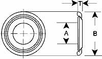
| Part Number | Maximum Shaft Diameter |
A | B | T |
| LTD0408 | 0.250 | 0.280 | 0.500 | 0.031 |
| LTD0510 | 0.312 | 0.344 | 0.625 | 0.031 |
| LTD0612 | 0.375 | 0.406 | 0.750 | 0.031 |
| LTD0714 | 0.437 | 0.468 | 0.875 | 0.031 |
| LTD0816 | 0.500 | 0.531 | 1.000 | 0.031 |
| LTD0918 | 0.562 | 0.593 | 1.125 | 0.063 |
| LTD1020 | 0.625 | 0.656 | 1.250 | 0.063 |
| LTD1122 | 0.687 | 0.718 | 1.375 | 0.063 |
| LTD1224 | 0.75 | 0.781 | 1.500 | 0.063 |
| LTD1326 | 0.812 | 0.843 | 1.625 | 0.063 |
| LTD1428 | 0.875 | 0.906 | 1.750 | 0.063 |
| LTD1530 | 0.937 | 0.968 | 1.875 | 0.063 |
| LTD1632 | 1.000 | 1.031 | 2.000 | 0.063 |
| LTD1834 | 1.125 | 1.156 | 2.125 | 0.063 |
| LTD2036 | 1.250 | 1.281 | 2.250 | 0.063 |
| LTD2240 | 1.375 | 1.406 | 2.500 | 0.063 |
| LTD2442 | 1.500 | 1.531 | 2.625 | 0.094 |
| LTD2644 | 1.625 | 1.656 | 2.750 | 0.094 |
| LTD2846 | 1.750 | 1.781 | 2.875 | 0.094 |
| LTD3048 | 1.875 | 1.906 | 3.000 | 0.094 |
| LTD3252 | 2.000 | 2.062 | 3.250 | 0.094 |
| LTD3654 | 2.250 | 2.312 | 3.375 | 0.094 |
| LTD4060 | 2.500 | 2.562 | 3.750 | 0.094 |
| LTD4466 | 2.750 | 2.812 | 4.125 | 0.094 |
| LTD4872 | 3.000 | 3.062 | 4.500 | 0.094 |
| LTD5278 | 3.250 | 3.312 | 4.875 | 0.094 |
Slim Pack Thrust Packs
FIBERGLIDE® Slim Pack thrust bearings are unique in the industry. They need no lubrication, can tolerate extremely high loads and require very little space. (Nominal thickness is only 1/8 in.) The advanced, patented design includes a self-contained dust seal and utilizes materials which resist corrosion. It provides its own smooth internal wear surface which is ideal where cast iron or other rough mating surfaces are present. Slim Pack thrust bearings are particularly suited for such applications as vehicle kingpin assemblies, and frame hinges.
Series FTP
Thrust Bearing Replacement Pack - Series FTT
A special thrust bearing is also available as a direct replacement for conventional ball or tapered bearings in certain applications such as kingpin assemblies. Contact Transport Dynamics Marketing Department directly for information.
Series FTT
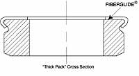
Cutaway view of Fiberglide® Series FTP Thrust Pack Diagram shows: A. Outer metal shell
B. Fiberglide® self-lubricating liner
C. Inner metal ring hard plate wear surface. Ring rotates against Fiberglide® liner which is bonded to outer shell.
| Part Number | A | B | T | Area |
| FTP1628 | 1.000 | 1.750 | 0.130 | 1.25 |
| FTP2032 | 1.250 | 2.000 | 0.130 | 1.48 |
| FTP2436 | 1.500 | 2.250 | 0.130 | 1.72 |
| FTP2638 | 1.625 | 2.375 | 0.130 | 1.84 |
| FTP2840 | 1.750 | 2.500 | 0.130 | 1.96 |
| FTP3244 | 2.000 | 2.750 | 0.130 | 2.19 |
| FTP3648 | 2.250 | 3.000 | 0.130 | 2.43 |
| FTP4052 | 2.500 | 3.250 | 0.130 | 2.66 |
| FTP4072 | 2.500 | 4.500 | 0.130 | 10.03 |
| FTP4874 | 3.000 | 4.625 | 0.130 | 8.72 |
Sealed Journal Bearings
FIBERGLIDE® SJR Series sealed journal bearings were developed for demanding applications in contaminated environments. Polyurethane seals are integral to the bearing and are highly resistant to abrasion and fluid contamination.
The standard product is supplied with FIBERGLIDE® self-lubricated bearing liners, polyurethane seals and a steel body. Other materials and sizes can be supplied. Consult Transport Dynamics Engineering Department. These components can also be supplied with single seals or without seals on special order.
* Recommended housing bores are for steel housings. Contact Engineering for recommended housing dimensions for alternate materials.
| Part Number | Maximum Shaft Diameter |
Recommended Housing Bore Min/Max |
Bearing Length |
| SJR1616 | 1.000 | 1.4984/1.5000 | 1.000 |
| SJR1620 | 1.000 | 1.4984/1.5000 | 1.250 |
| SJR1624 | 1.000 | 1.4984/1.5000 | 1.500 |
| SJR1632 | 1.000 | 1.4984/1.5000 | 2.000 |
| SJR2016 | 1.250 | 1.7484/1.7500 | 1.000 |
| SJR2020 | 1.250 | 1.7484/1.7500 | 1.250 |
| SJR2024 | 1.250 | 1.7484/1.7500 | 1.500 |
| SJR2032 | 1.250 | 1.7484/1.7500 | 2.000 |
| SJR2416 | 1.500 | 1.9982/2.0000 | 1.000 |
| SJR2420 | 1.500 | 1.9982/2.0000 | 1.250 |
| SJR2424 | 1.500 | 1.9982/2.0000 | 1.500 |
| SJR2432 | 1.500 | 1.9982/2.0000 | 2.000 |
| SJR2816 | 1.750 | 2.2482/2.2500 | 1.000 |
| SJR2824 | 1.750 | 2.2482/2.2500 | 1.500 |
| SJR2832 | 1.750 | 2.2482/2.2500 | 2.000 |
| SJR2840 | 1.750 | 2.2482/2.2500 | 2.500 |
| SJR3216 | 2.000 | 2.4982/2.5000 | 1.000 |
| SJR3220 | 2.000 | 2.4982/2.5000 | 1.250 |
| SJR3224 | 2.000 | 2.4982/2.5000 | 1.500 |
| SJR3232 | 2.000 | 2.4982/2.5000 | 2.000 |
| SJR3616 | 2.250 | 2.7482/2.7500 | 1.000 |
| SJR3624 | 2.250 | 2.7482/2.7500 | 1.500 |
| SJR3632 | 2.250 | 2.7482/2.7500 | 2.000 |
| SJR3648 | 2.250 | 2.7482/2.7500 | 3.000 |
| SJR4024 | 2.500 | 2.9982/3.0000 | 1.500 |
| SJR4032 | 2.500 | 2.9982/3.0000 | 2.000 |
| SJR4040 | 2.500 | 2.9982/3.0000 | 2.500 |
| SJR4048 | 2.500 | 2.9982/3.0000 | 3.000 |
| SJR4424 | 2.750 | 3.4978/3.5000 | 1.500 |
| SJR4432 | 2.750 | 3.4978/3.5000 | 2.000 |
| SJR4448 | 2.750 | 3.4978/3.5000 | 3.000 |
| SJR4824 | 3.000 | 3.7478/3.7500 | 1.500 |
| SJR4832 | 3.000 | 3.7478/3.7500 | 2.000 |
| SJR4848 | 3.000 | 3.7478/3.7500 | 3.000 |
| SJR5632 | 3.500 | 4.2478/4.2500 | 2.000 |
| SJR5648 | 3.500 | 4.2478/4.2500 | 3.000 |
| SJR5656 | 3.500 | 4.2478/4.2500 | 3.500 |
| SJR6432 | 4.000 | 4.7475/4.7500 | 2.000 |
| SJR6448 | 4.000 | 4.7475/4.7500 | 3.000 |
| SJR6464 | 4.000 | 4.7475/4.7500 | 4.000 |
| SJR7232 | 4.500 | 5.2475/5.2500 | 2.000 |
| SJR7248 | 4.500 | 5.2475/5.2500 | 3.000 |
| SJR7264 | 4.500 | 5.2475/5.2500 | 4.000 |
| SJR8040 | 5.000 | 5.7475/5.7500 | 2.500 |
| SJR8048 | 5.000 | 5.7475/5.7500 | 3.000 |
| SJR8064 | 5.000 | 5.7475/5.7500 | 4.000 |
Engineering Data
Many factors affect the overall performance of FIBERGLIDE® bearings. Those of primary concern include applied load, surface velocity, operating mode, surface temperature, mating surface finish and running clearance. All performance values referred to in this section are based on dry operation. When running in a fluid atmosphere, FIBERGLIDE® bearings may have limitations. Where application requirements exceed those shown, consult Transport Dynamics engineering department for specific recommendations. FIBERGLIDE® lined bearings are designed to be used under oscillating motion, interrupted start-stop, or axial motion. They are recommended where high loads are combined with low surface speeds.
Design Calculations
Proj. Area (sq.in.) = Shaft Dia. Max (or Nom. I.D.) x length
P Pressure (psi) = Load (Lbf) ÷ by Proj. Area
V. Velocity (FPM) = Shaft Dia. Max x /12 X 4 x osc. Angle° x CPM/360
CPM=cycles per minute (journals-oscillating motion)
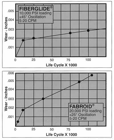
Bearing Wear
Bearing wear is affected by many factors. For the most part, tests conducted by Transport Dynamics subject journal bearings to 20,000 psi loads with the bearing fixed and the shaft oscillating. The values shown in the charts on page 6 are representative of the normal wear rate range that can be expected when amplitude is ±45°, frequency is 10 CPM, and shaft finish is 16 RMS under room temperature conditions. It will be noted that a wear-in period takes place during the first few thousand cycles. During this period some PTFE is transferred to the mating surface. In addition, the fibers are generally reoriented, the high points of the weave are flattened and adjacent fibers tend to blend together. After the break-in period, the bearing surface will become smooth and shiny. Because of the many variables which influence wear, it is extremely difficult to project bearing life for all types of applications. For this reason, the Transport Dynamics Engineering Department should be consulted when questions of this nature arise. Wear life calculations are based on rubbing distance of travel.
Bearing Load Limits
Static Pressure Limit (Constant pressure*)
10,000 psi with phenolic backing
30,000 psi with steel backing
Dynamic pressure limits while oscillating
20,000 psi suggested maximum.
Velocity Limit
Under dry running conditions, the maximum allowable surface velocity will depend on the applied load and other operating parameters. In general, surface speed should be kept below 35 FPM (Feet Per Minute) at 10,000 psi load or 600 FPM at 100 psi load.
PV Factor
For plain, dry-running bearings, it is often helpful to reference a pressure-velocity (PV) factor as a guide in determining bearing capability. It should be understood that this factor is actually a variable which reflects the point where surface temperatures are at a maximum, but are still stable. The maximum PV established for FIBERGLIDE® is:
PV continuous-60,000
PV intermittent-150,000
Temperature Limit
Normal operating temperatures should be kept below 300°F for standard FIBERGLIDE® bearings. An increase in wear rates may be experienced at temperatures above 350°F. Note that at elevated operating temperatures, the PV limit will be decreased in order to prevent the surface temperature from exceeding 300°F, (environmental temperature plus friction heat generated). When temperatures exceed 300°F or fall below -200°F, consult Transport Dynamics Engineering Department for specific recommendations.
Coefficient of Thermal Expansion
When bonded to a metal backing, FIBERGLIDE®'s coefficient of expansion can normally be regarded as identical to that of the backing, with steel backing 8.4 x 10⁶ in/in/°F.
Mating Surfaces
FIBERGLIDE®, being non-metallic, will operate against most metals, but better performance is obtained with the hardest available mating surfaces. Hardened steel, hard anodized aluminum, hard chrome or nickel plate are recommended. A surface hardness of 45-50 Rc is desirable, but satisfactory performance can also be obtained with softer materials. Generally, a surface finish on the mating components of 16-32µ inch should be provided. Shaft materials or surface treatments should be selected that will effectively resist corrosion. Transport Dynamics recommends a max surface finish of 32 Rms and minimum hardness of 40Rc.
To determine the approximate reduction in life for different values of shaft finish and hardness, see below.
| Surface Finish µ in. | Life Factor |
Hardness Rockwell Reading |
Life Factor |
|---|---|---|---|
| 8-16 | 1.00 | Rc50 | 1.00 |
| 32 | 0.55 | Rc40 | 0.60 |
| 63 | 0.20 | Rc30 | 0.40 |
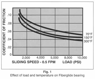
Coefficient of Friction
Coefficient of friction depends upon type of movement, finish of mating surface, ambient temperature, bearing pressure, velocity and other variables. Figs. 1,2, and 3 were obtained from flat specimens and may be used as a guide. Note in Fig. 1 that the coefficient drops off as bearing load increases. This offers the advantage of using the smallest bearing sizes to obtain the least amount of friction. Fig. 3 shows the coefficient of friction increasing as surface velocity increases from 2-20 FPM. This feature is particularly valuable for vehicle steering systems.
Contamination
FIBERGLIDE® can tolerate small amounts of dirt, but reduced bearing life will result. Optimum life is achieved if dirt or abrasive particles are excluded. If a dirty environment is likely, we recommend installation of a simple seal.
Running Clearance
As a general rule, close running fits, and often slight interference fits (.0005 in.) are selected for oscillating motion when minimum starting torque is less important than the elimination of free play. For constant rotation, a free-running fit is normally recommended, the exact amount depending on bearing bore size. A rule of thumb would be 0.0015 inches per inch of bore ( bearing installed).
Bearing Housing and Shaft Sizing
Standard FIBERGLIDE® journal bearings (CJS/CJT/CJM/CJH/SJR Type) are installed into the housing bore using a press fit. Recommended housing bores should be held to the tolerance shown to insure the proper fit and size.
The LJS Type bearing is hand slip fit into its recommended housing bore to provide optimum fit-up. CJS/CJT/CJM/CJH types can also be provided for slip fits on special order.
RBC Transport Dynamics offers a special service to properly size housing and shaft for each new application. Contact RBC Transport Dynamics Engineering Department for details.
Fluid Compatibility
FIBERGLIDE® can tolerate most fluids or contaminants found in bearing applications, although some reduction of dry bearing life will result. Fluids tend to flush PTFE solid particle lubricants out of the bearing. Grease tends to act as a magnet to attract and retain dirt. Following are some of the environments in which these bearings have operated successfully:
- Hydraulic Oils
- Mild acids
- Greases
- Gasoline
- Lubricating oils
- Detergent solutions
- Ammonium hydroxide
- Liquid Nitrogen
- Seawater
- Toluene
- Kerosene
Metric Technical Data Conversions
FIBERGLIDE® Bearing Load Limits: |
|||||
Static Pressure Limits (Constant) |
|||||
Phenolic Backed: |
10,000 psi = 69 N/mm² | ||||
Steel Backed: |
30,000 psi = 207 N/mm² | ||||
Dynamic Pressure Limits (Oscillating) |
|||||
Phenolic Backed: |
10,000 psi = 69 N/mm² | ||||
Steel Backed: |
20,000 psi = 138 N/mm² | ||||
Velocity Limit: |
|||||
| Surface Speed Should be Kept Below 35 ft/min at 10,000 psi = 0.175 m/s at 69 N/mm² | |||||
| or 600 ft/min at 100 psi = 3 m/s at 0.69 N/mm² | |||||
PV Factor: |
|||||
| Max Continuous PV | 60,000 psi-ft/min = | 2.07 N/mm²-m/s | |||
| Max Intermittent PV | 150,000 psi-ft/min = | 5.175 N/mm²-m/s | |||
| Temperature Limit: | |||||
Normal Operating Temperature Should Be Kept Below 300°F = 149°C |
|||||
Increased Wear Rates May Be Experienced Above 350°F = 177°C |
|||||
Consult TD Engineering Dept. When Temperature is Below -200°F = -129°C |
|||||
Mating Surfaces: |
|||||
| Surface Finishes | 8 µ in = 0.2 µ m | ||||
| 16 µ in = 0.4 µ m | |||||
| 32 µ in = 0.8 µ m | |||||
| 63 µ in =1.6 µ m | |||||
Running Clearance: |
|||||
| Slight Interferrence Fit Recommended for Oscillating Motion | .0005 in = .0127 mm | ||||
| Free-Running Fit Recommended for Constant Rotation | .0015 in/in of bearing ID | .0015 mm/mm of bearing ID | |||
Test Conditions: |
|||||
| Bearing ID | 1.00 in = 25.4 mm | ||||
| Bearing Length | 0.50 in = 12.7 mm | ||||
| Bearing Loads | 2,500 lb = 562.5 N | ||||
| 5,000 lb = 1125 N | |||||
| Bearing Pressures | 5,000 psi = 34.5 N/mm² | ||||
| 10,000 psi = 69 N/mm² | |||||
FIBERGLIDE®-Fabroid: |
|||||
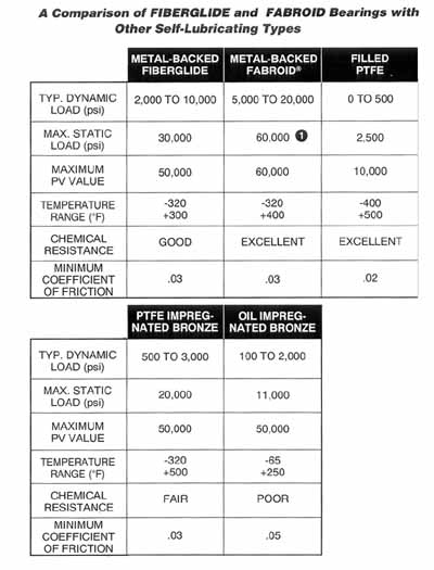
| A Comparison of FIBERGLIDE® and FABROID Bearings with Other Self-Lubricating Types | |||||
| Metal-Backed FIBERGLIDE® | Metal-Backed Fabroid | Filled PTFE | PTFE Impreg-nated Bronze | Oil Impreg-nated Bronze | |
| Typ. Dynamic Load (psi) | 2,000 to 10,000 | 5,000 to 20,000 | 0 to 500 | 500 to 3,000 | 100 to 2,000 |
| Typ. Dynamic Load (N/mm²) | 13.8 to 69 | 34.5 to 138 | 0 to 3.45 | 3.45 to 20.7 | 0.69 to 13.8 |
| Max. Static Load (psi) | 30,000 | 60,000 1) | 2,500 | 20,000 | 11,000 |
| Max. Static Load (N/mm²) | 207 | 414 | 17.25 | 138 | 75.9 |
| Maximum PV Value (psi-ft/min) | 50,000 | 60,000 | 10,000 | 50,000 | 50,000 |
| Maximum PV Value (N/mm²-m/s) | 1.725 | 2.07 | 0.345 | 1.725 | 1.725 |
| Temperature Range (°F) | -320 to +300 | -320 to +400 | -400 to +500 | -320 to +500 | -65 to +250 |
| Temperature Range (°C) | -196 to +149 | -196 to +204 | -240 to +260 | -196 to +260 | -54 to +121 |
| 1) For Low Speed Oscillating Conditions-static loads over 30,000 psi (N/mm²) or dynamic loads over 20,000 psi (N/mm²) require metal backing of high strength stainless steel or equivalent materials. | |||||
Bearings-Installation: |
|||||
| Journal Bearings | |||||
| Min. Housing Lead-in Chamfer | .050 in = 1.27 mm | ||||
| Min. Shaft Lead-in Chamfer | .125 in = 3.175 mm | ||||
| or | |||||
| Min. Shaft Corner Radius | .060 in = 1.524 mm | ||||
| Thrust Bearings | |||||
| Allowable Corner Radius of Stepped Shafts Through ID of |
|||||
| FTS | .015 in = .381 mm | ||||
| LTD | .030 in = .762 mm | ||||
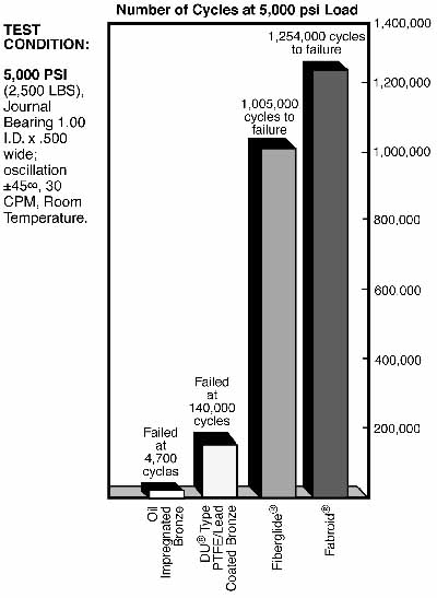
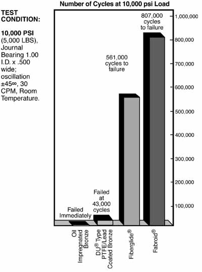
Tests
Tests were conducted to compare the load carrying capability and wear life of four standard self-lubricating bearing products. Transport Dynamics performed all testing on the same test machine and fixturing. Standard FIBERGLIDE® and FABROID® products are presented herein. Transport Dynamics offers other self-lubricating bearing products capable of dynamic loading to 40,000 psi and ultimate static loading to 120,000 psi.
Test Conditions
The bearings were placed under a fixed load with an oscillating shaft. The test bearing size was 1.00 inch I.D. by .500 inches long. The test conditions were 10,000 psi (5,000 lbs.) and 5,000 psi (2,500 lbs.) loads with an oscillation of +/- 45 degrees and 30 cycles peer minute at room temperature. Approximately every 10,000 cycles, the bearings were removed and inspected for wear.
Industrial Bearing Life Testing
Cycles to Failure vs. Bearing Type
DU® is a registered trademark of Garlock Bearings, Inc.
FIBERGLIDE® - Fabroid®
The graphs below are typical wear curves for two types of self-lubricating liner materials; Standard FIBERGLIDE® A, and FABROID® G. The standard FIBERGLIDE® A material is suitable for most applications and significantly outperforms other bearing types. But, should your application include extraordinarily high static and/or dynamic loads, extremes of temperature, or chemical resistance requirements, Transport Dynamics manufactures a variety of liner materials and backing for critical service applications. There are two types of FIBERGLIDE® liners depending on the product configuration and three types of FABROID®.
Transport Dynamics is the originator, innovator and leader in self-lubricating bearing technology with over thirty years of material development and application experience. The original Fabroid® Liner System was patented in 1958. Evolution in the development of materials has created three generations of self-lubrication liner technology.
Today's materials represent a significant advance in technology and their increased capabilities offer solutions in applications previously judged to be borderline or beyond material capability. Contact Transport Dynamics Engineering Department for a detail publication of all our liner systems. Request Engineering Bulletin #106, Bearing Design Guide.
FOR LOW SPEED OSCILLATING CONDITIONS - static loads over 30,000 psi or dynamic loads over 20,000 psi require metal backing of high strength stainless steel or equivalent materials.